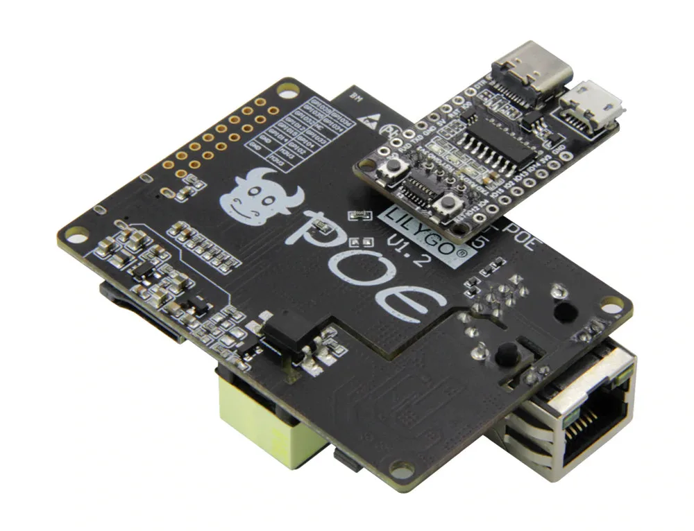
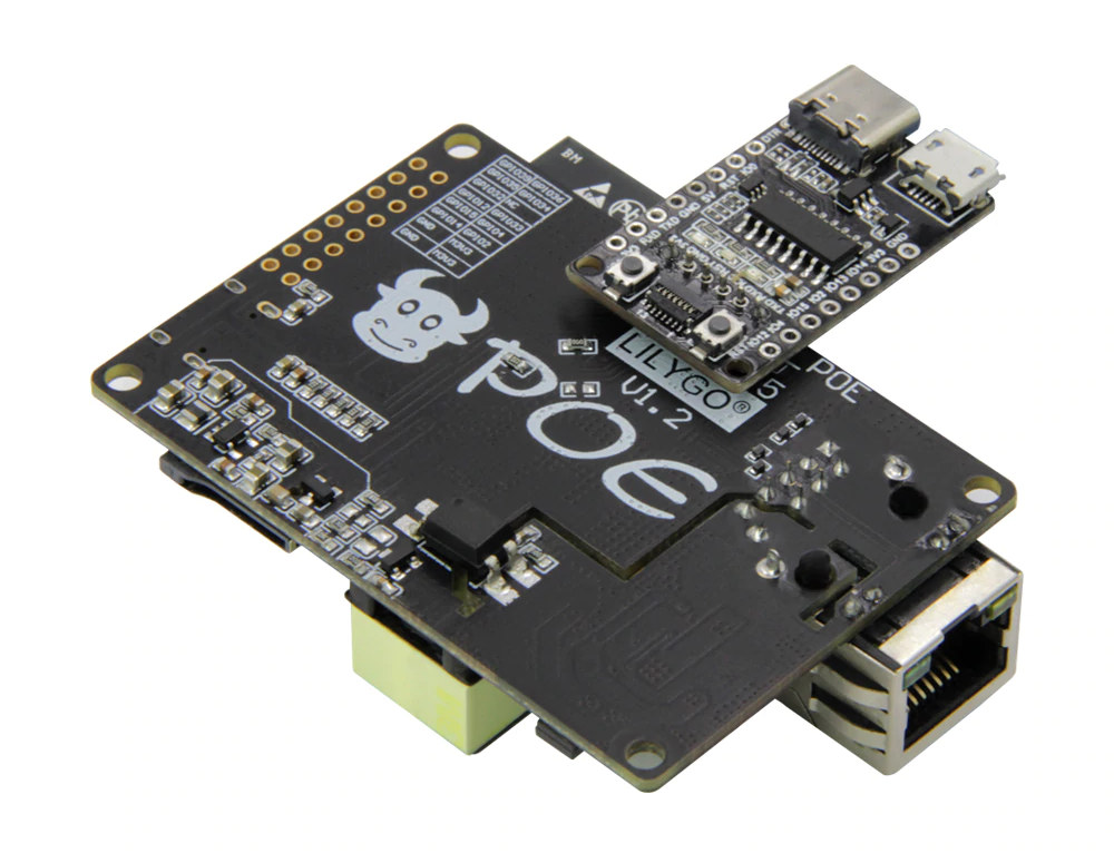
Having a new LilyGO TTGO ESP32 arrive, I got to work on flashing it with Tasmota straight away. A bit fiddly as you need to connect the download board, which gives us the CH340 USB to Serial we need.
This wasn’t as straight forward, and I had to play with it some more. I’m not using PoE right now, just powering it with 5v from USB C and using a regular Ethernet switch port. Tooks some reading to find that the settings I needed to make in user_config_override.h contradicted what I was using for the WT32-ET01, even though it’s supposed to be the same Ethernet adapter.
I found the clue here: https://github.com/Xinyuan-LilyGO/LilyGO-T-ETH-POE/blob/master/example/eth/eth.ino
The github post showed that the setting used GPIO17
#define ETH_CLK_MODE ETH_CLOCK_GPIO17_OUTThat meant I needed to change the ETH_CLKMODE to 3 and then restart.
#define USE_ETHERNET
// Wireless-Tag WT32-ETH01
#define ETH_TYPE 0    // [EthType] 0 = ETH_PHY_LAN8720, 1 = ETH_PHY_TLK110, 2 = ETH_PHY_IP101
#define ETH_ADDRESS 1 // [EthAddress] 0 = PHY0 .. 31 = PHY31
#define ETH_CLKMODE 3 // [EthClockMode] 0 = ETH_CLOCK_GPIO0_IN, 1 = ETH_CLOCK_GPIO0_OUT, 2 = ETH_CLOCK_GPIO16_OUT, 3 = ETH_CLOCK_GPIO17_OUT
I found I could also test these settings out at the console using:
EthType 0
EthAddress 0
EthClockMode 3
I had a eureka moment as I got it fired up though - more of a negative realisation than eureka. If I am to use this on the Gatekeeper project, I need 12v DC to power the keypad and fire the latch on the door striker. Using PoE - how am I going to do that?
If I use a PoE injector I can separate 12v DC, pipe it through a buck convertor and get it to provide both 12v for the striker and 5v to power the ESP. I can’t do that with a full PoE implementation.
So far this board gave me some challenges, mostly no 12v DC. That means it goes into the parts box until I find a different project to use it with.